Executive Summary
- More serious issues, that First-Responders won't be handling
- Longer downtime of helium compressor
- Higher Mimir vacuum states
- Cold head contamination -> partial warm-up purge
- Helium system 'topping off'
- Getter clearing (~TBD)
- Compressor fuse changes (~TBD)
- Evaluating compressor failures (TBD)
- Mimir warm-ups (TBD)
- Mimir long pump outs (TBD)
- Mimir cool-downs (TBD)
- Critical Aspects
- Mimir/compressor/helium lines system runs on 99.999% pure helium gas – contamination MUST be avoided
- Mimir's cryostat vacuum valve MUST be closed for ANY vacuum state change or power failure
- Helium manifold and connection lines MUST be helium-purged prior to connecting to units
- Communications
- Longer than usual compressor downtime -> txt to Dan Clemens ASAP, preferably before starting intervention
- Any other issues -> call or Skype with Dan Clemens, BEFORE actions
- Problems beyond routine, CALL Dan Clemens (781-492-2726)
Key Web Pages and Links:
- Mimir Status – LUX (within Lowell firewall) = http://lux.lowell.edu/mimir/mimir_status.html
- Mimir Status – IAR (outside Lowell firewall) = http://iar.lowell.edu/mimir/
- Compressor Status (w/i Lowell only) = http://compressor.lowell.edu/current-values-control.htm
- Compressor Shed WebCam = https://www.samsungsmartcam.com/web/ (must create your account)
- Cam Name = 'Compressor Shed' (no quotes)
- Cam S/N = KHNL6V2G7002CBM
- Cam Password = 'mimir123' (no quotes)
Dan Clemens Contact Info:
- Email -> clemens_dp@comcast.net, clemens@bu.edu
- Phone, Txt, FaceTime: 781-492-2726
- Home: 781-444-6478
- Skype -> dan.clemens
Connecting Vacuum Pumps to Mimir, Pumping, Removing Vacuum Pumps
- Be sure the Mimir cryostat vacuum valve is closed
- Do NOT overtighten – fingertip tight, only
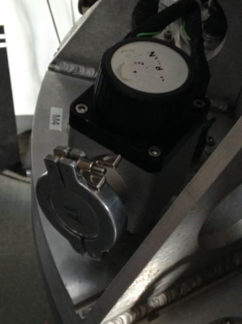
- Remove NW40 cover plate and capture ring on Mimir vacuum valve
- Remove NW40 cover on Turbo pump
- Position Turbo to attach to Mimir vacuum valve, using captured O-ring and capture ring

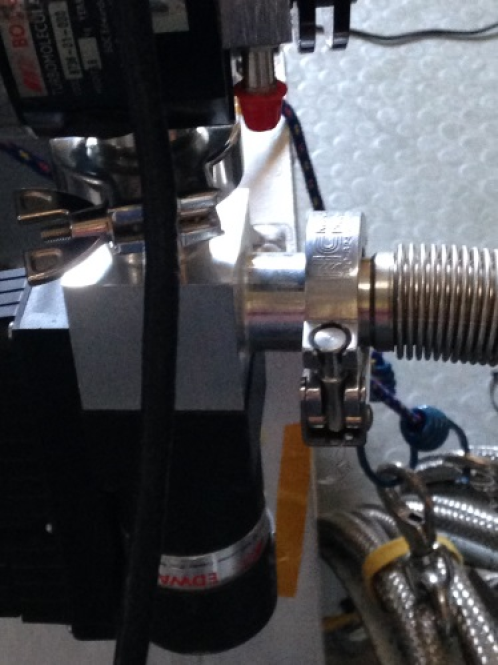
- Emergency valve, attached to NW25 exit of Turbo, should be oriented vertically:
- Attach NW25 flexible vacuum hose to exit of Emergency Valve
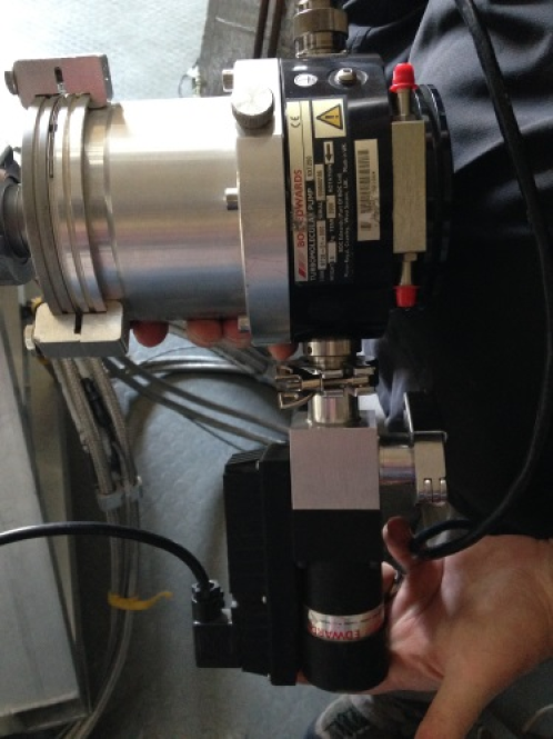
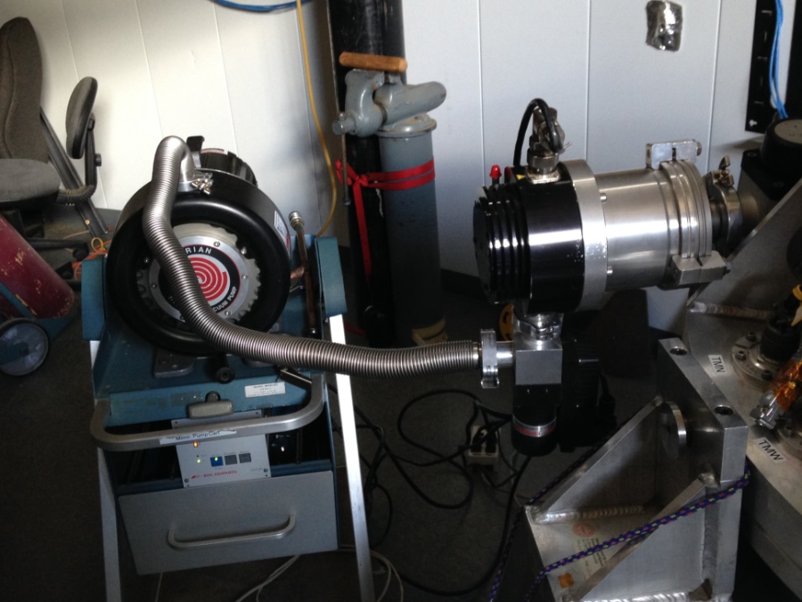
- Fully connected Turbo, Emergency Valve, and flexible vacuum hose should look like this:
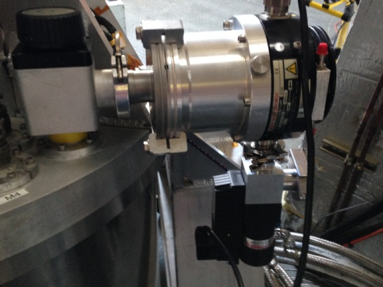
- The full vacuum system should look like this:
Starting the Vacuum System
- Check that the Mimir vacuum valve is closed (yes, again!)
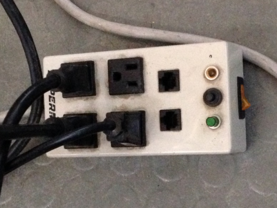
- The Scroll pump, Emergency Valve, and Turbo pump controller should all be plugged into the 2x2 relay controlled multi-outlet box:
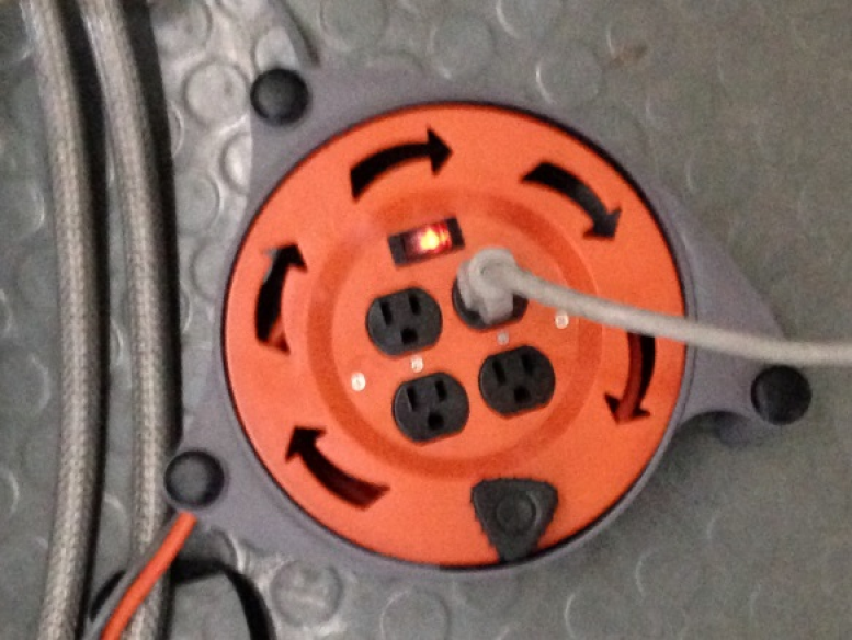
- Plug the cord from this box into an extension cord, such as the 2x2 outlet box with rotary take up reel:
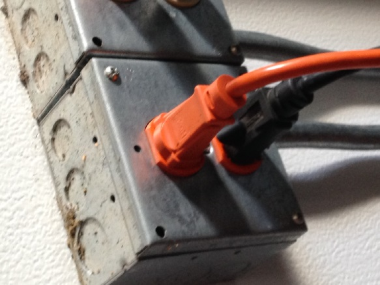
- Plug the power cable from this extension cord into an ORANGE power outlet in the Perkins dome:
- Start the Scroll pump (which also opens the emergency valve) by turning on the orange rocker switch on the relay-protected outlet box and pressing the black button on front of that box:
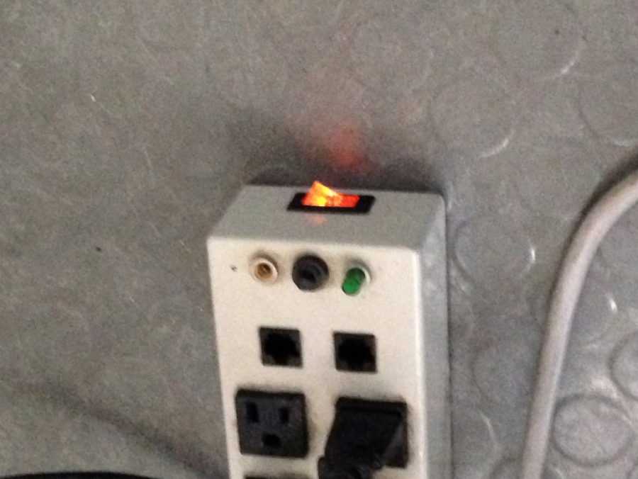
- This relay-protected outlet box is used to turn off power to the emergency valve in the case of a power failure. This provides vacuum integrity protection for Mimir in the event of a power failure.
- Under NO circumstances should you repower this relay-protected outlet box while the Mimir cryostat vacuum valve is open.
- If a power failure has occurred, CLOSE the Mimir cryostat vacuum valve FIRST.
- After about 2 minutes, the Scroll pump should have brought the vacuum in the Turbo pump low enough to allow starting the Turbo.
- To start the Turbo, on the Turbo controller unit (see pic below), press the "START" button:
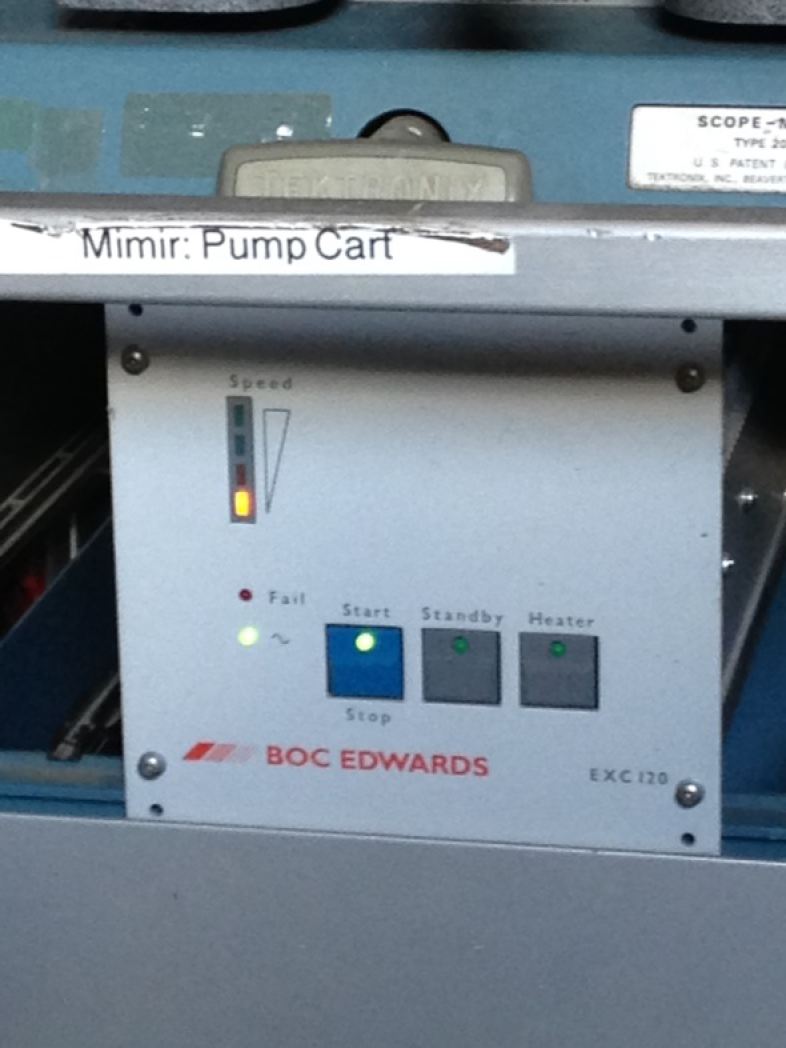
- This will start the Turbo spinning.
- Putting an ear on the Turbo should confirm it is spinning up
- If it sounds like a 'box of rocks' or makes loud noises for longer than 20 seconds, press "START" again to turn it off. Call Dan Clemens.
- The LED indicator on the Turbo controller shows the Turbo speed.
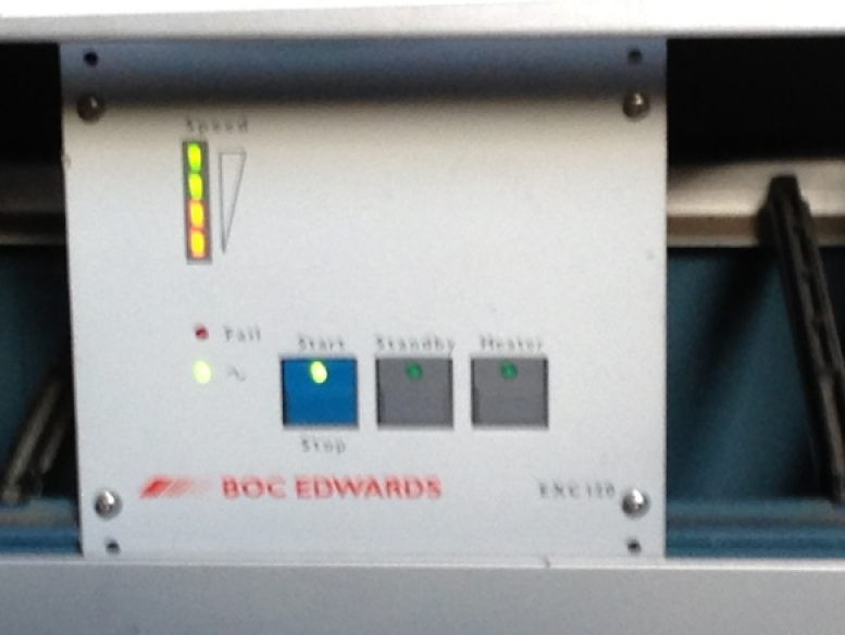
- Wait until all 4 LEDs are lit on the indicator (this could take up to 10 min):
- Turn on Mimir's BA Vacuum Gauge and let it settle.
- Open Mimir's cryostat vacuum valve
- The pressure should be dropping
- Continue vacuum pumping
- If Mimir is cold, a good pressure target is about 10-7 to 10-8 torr
- If Mimir is warm, aim for 10-6 to 10-7 torr
- When vacuum pumping has reached vacuum goal, close the Mimir cryostat vacuum valve (lightly…)
- Turn off the Turbo, by pressing the "START" button on the BOC Edwards Turbo controller
- Wait for the Turbo to spin down – this might take 15 minutes
- Turn off the Scroll and Emergency valve using the rocker switch on the relay-protected outlet box
- Disconnect the NW25 flexible host to the Emergency valve
- Cap the hose
- Cap the Emergency valve
- Disconnect the Turbo from the Mimir cryostat vacuum valve
- Cap the Mimir vacuum valve
- Cap the Turbo
- Return the Turbo+Emergency Valve to the vacuum cart, disconnect the relay-protected outlet box from the extension cord.
- If winter, return the vacuum cart to the warm room off of the control room
Cold Head Warm Purge
- The helium cold head traps contaminants in the helium cooling system, and 'ices' up as a result, which affects its cooling power, especially for the 2nd stage.
- This action will warm the getter and detector in the cryostat, so attach the Turbo+E-Valve+Scroll vacuum pumping system, get it fully going, but don't open the Mimir cryostat valve until in a later step.
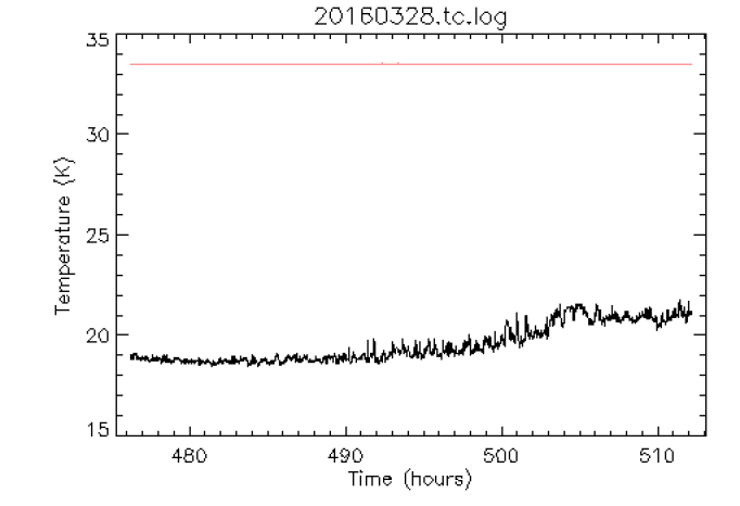
This is a plot of the detector (pink line at 33.5K) and the cold head 2nd stage temperature (black line), showing a rise to 21 K. It should normally be 16-18 K, so this rise (and the associated thermal 'noise') is indicating the 2nd stage is icing up.
- A 'Warm Purge' is a poor, but necessary way to get some of the ices out while Mimir remains cold.
- Water ice will not be removed, but oxygen, nitrogen, CO2, and argon will. These latter species dominate contamination.
- If the Remote-Operated-Circuit-Breaker (ROCB) is working to control the helium compressor power, then this can be done as a single-person job. If the ROCB isn't working (as is the status today), then this is a two-person job.
- In the Compressor Shed, be sure the high-purity helium bottle on the bottle cart is valved off.
- Move the bottle on its cart (including the attached hoses and manifold) into the Perkins building, onto the elevator, and elevate it up to the observing floor. Move it close to Mimir's helium cold head:
- Find the two large box wrenches in the small red tool box that normally is near/on/under the Mimir electronics rack or white support cart. These will be used to remove the helium hoses while preventing them from twisting.
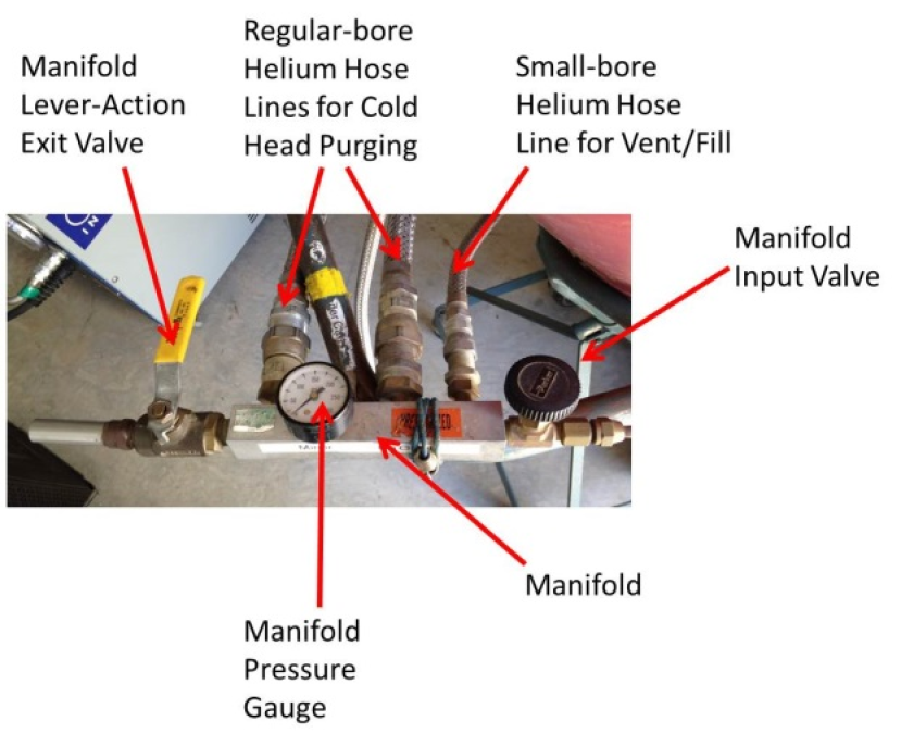
Helium purge the manifold and hoses attached to the high-purity helium bottle:
Close all 4 valves
- The valve at the helium bottle
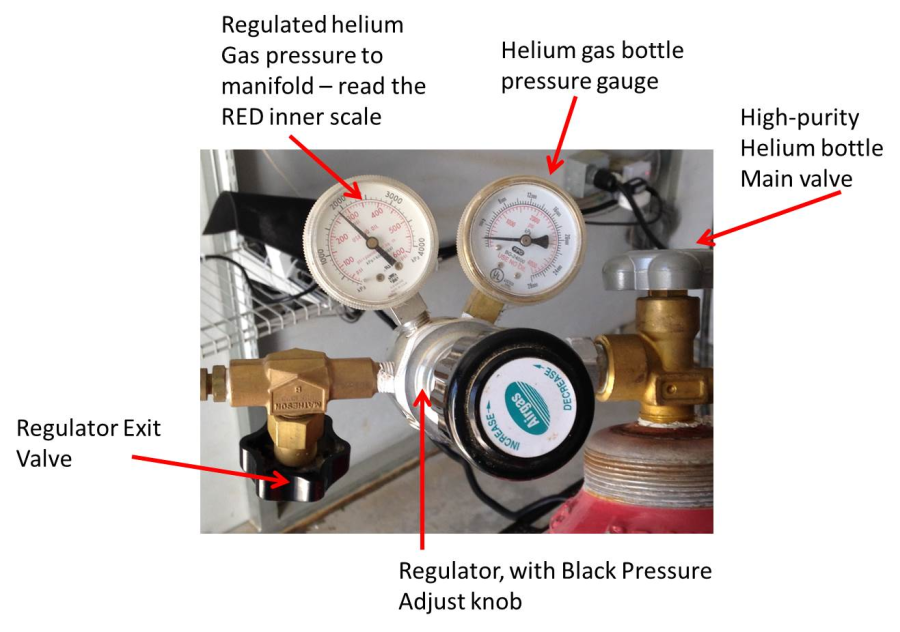
- The valve on the exit end of the regulator
- The input valve to the manifold
- The exit lever-action valve on the manifold
- Open the helium bottle valve
- Set the regulator, if necessary, to 250psi
- Open the regulator exit valve
- Open the manifold input valve
- The manifold pressure gauge should rise up to about 250 psi
- Close the regulator exit valve – this isolates the helium supply from the gas in the manifold
- Slowly open the lever-action valve, while watching the manifold gauge
- Vent gas until the manifold gauge pressure is 30psi and then quickly close the lever-action valve
- Open the regulator exit valve to flow gas back into the manifold to bring it back to 250psi.
- This constitutes '1 cycle' of purging of the manifold.
- Repeat for 19 more cycles to flush all contaminants out of the hoses and manifold prior to attaching to the cold head.
- Using the ROCB (if it is working) or a partner, turn off the helium compressor
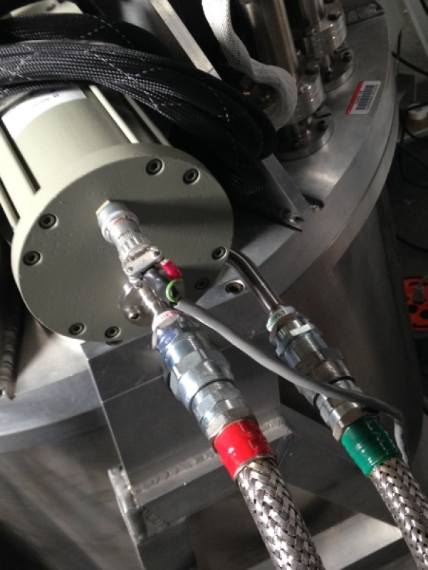
- Using the two wrenches, work quickly to detach the red (return) helium hose from the cold head
- Keeping the hoses straight (not bent) will make this go easier and will help prevent loss of helium
- Then, quickly detach the green (supply) helium hose from the cold head
- Attach one helium hose from the manifold to the supply side of the cold head
- Attach a second helium hose from the manifold to the return side of the cold head
- Use the lever-action valve to drop the manifold pressure to 30psi, then close the lever-action valve
- Open the regulator exit valve to flow helium into the manifold and cold head
- Repeat this for 4 more cycles of fill and venting of helium, leaving the cold head pressurized to 250psi at the end of the cycles
- Using the ROCB, or the 2nd person, restart the compressor for 30 seconds, then turn it off
- If the cold head power cable was not detached, you should hear the cold head displacer move
- If you detached the cold head power cable, re-attach it and explain to the 2nd person why they have to go back into the shed…
- Repeat the fill-purge process for 5 cycles
- Restart the compressor for 30 seconds, then turn off.
- Repeat the fill-purge
- The goal is 25 total fill-purge cycles, with the cold head moving (under compressor power) after every 5 cycles.
- After all cycles are completed, be sure the cold head is re-pressurized to 250psi.
- Detach the helium lines of the manifold from the cold head
- Re-attach the helium lines from the compressor to the cold head
- Restart the compressor
- Close the bottle valve to the high-purity helium bottle, close the regulator exit value, close the other two valves.
- Return the bottle, cart, and manifold with hoses back to the helium compressor shed
Topping off the helium system
- Helium always leaks out of closed systems, and ours is no exception. So, high-purity helium must be added back to keep the working gas pressure at nominal values
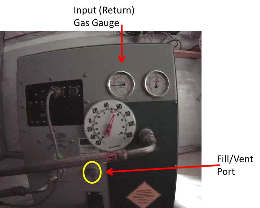
- Examine the input (return) helium gas pressure gauge value on the compressor face.
- If the pressure is higher than 60 psi, nothing needs to be done
- If the pressure is at 60 psi or lower, topping off is necessary
- If the pressure is below 30 psi, there is a serious problem – immediately call Dan Clemens
- If topping-off is needed, follow the same manifold helium purging process described above, so that there are no contaminants in the manifold and hoses.
- Remove the cap to the small fill/vent hose receptacle on the compressor face:
- Be sure the manifold is pressurized and the three rotary valves are all open (ie, leave the lever-action valve closed), so that helium will flow.
- Uncap the small bore helium hose from the manifold
- Close the exit valve from the regulator
- Turn the compressor off and let the two compressor gauges come to equilibrium with each other
- Attach the small bore hose to the fill/vent port
- While watching the compressor gauges, open the regulator exit valve to flow helium
- Continue until the compressor gauges register 240 psi, then close the regulator exit valve
- Disconnect the small bore helium hose from the compressor fill/vent port
- Cap the fill/vent port
- Re-start the helium compressor
- Cap the small bore helium hose
- Read and record the pressure in the helium bottle.
- If below 600 psi, re-order more high-purity helium (via Len Bright)
- Close the helium bottle valve, the regulator exit valve, and the manifold input valve
- Tidy up the manifold and hoses, and push the helium bottle cart into the shed corner
Getter Clearing – DRAFT – NOT READY TO BE FOLLOWED YET
- This would normally be done if the helium compressor has been off for a long time, the cryostat pressure has risen to a high value, and the vacuum pumps are actively working on pumping down on the Mimir volume.
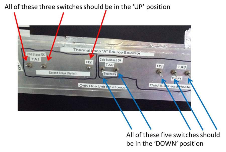
- On the back of the Mimir electronics, set the heater and temperature switches to point the temperature controller (the LakeShore LS331) TA loop system to the 2nd stage.
- Turn on the BA vacuum gauge, if it isn't already on
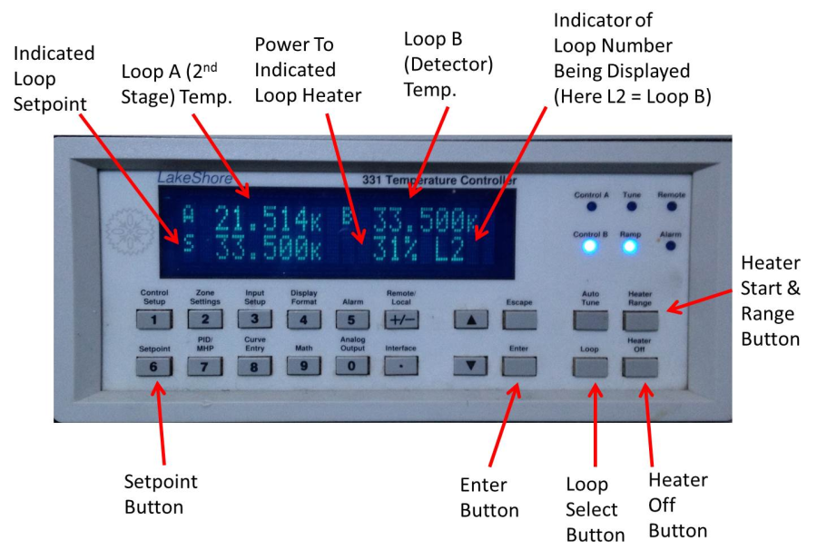
- Find the LS331 temperature controller in the Mimir Electronics Rack
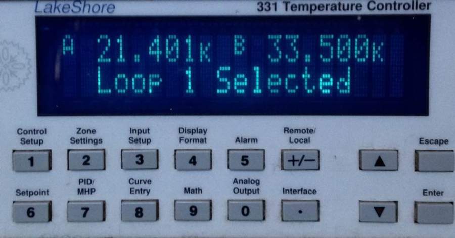
- Press the "Loop" button to select 'Loop 1' (the A loop).
- The display should show "Loop 1 Selected'
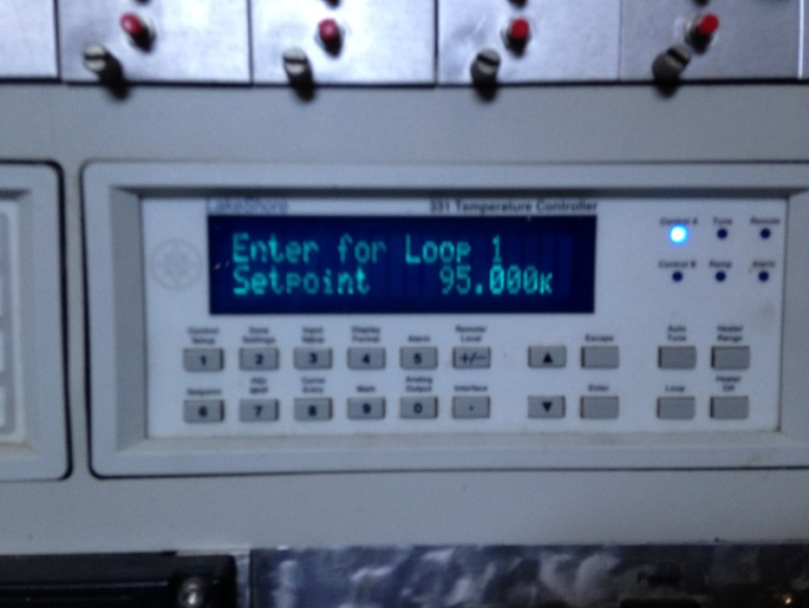
- Press the 'Setpoint' button to initiate setpoint selection
- Use the keypad to key in '100' to put the set point at 100K
- There is no advantage to going higher than this when Mimir is cold
- Press the 'Enter' button
- Press the 'Loop Power' button until it says 'High'
- Press the 'Enter' button to fix this setting
- This should begin the warming of the getter, which is attached to the second stage
- The temperature readouts should show increases
- The BA gauge should show pressures rising
- Continue in this configuration until the pressures have ceased to rise, have flattened with time, and finally gone down; usually about 30 minutes or so
- Usually, they will go down from their peak by 1-2 orders of magnitude in pressure
- When done, press the 'Heater Off' button to turn the heater off
- Continue vacuum pumping, watching the pressures continue to decrease as the getter and other surfaces cool.
- Close the Mimir cryostat valve when pressures are below 10-6 – 10-7 torr.
- Begin vacuum system shutdown (Turbo spin-down, etc, see instructions above)
- Restart helium compressor, if appropriate.
Changing Fuses Within the Compressor
- Fuse failures have tended to be either the fan fuses (two fans, so 2 fuses) or the fuse for power to the cold head
- Both sets of fuses are currently located WITHIN the helium compressor unit
- When fan fuses fail, the compressor overheats, triggers a thermal sensor, and shuts down.
- The diagnostics of this condition are full 3-phase power, normal ambient shed temperatures, and an inability to keep the compressor running for very long. The shed logger unit may also be sending high compressor temperature alarms.
- Be sure to unplug the 3-Phase compressor power from the wall outlet BEFORE opening the compressor cover(s)
- Remove the screws holding the left (South-facing) compressor cover and set the cover aside
- Note the gold/bronze closed electronics box that is mated to the compressor front (East-facing) cover.
- You do NOT need to open this electronics box
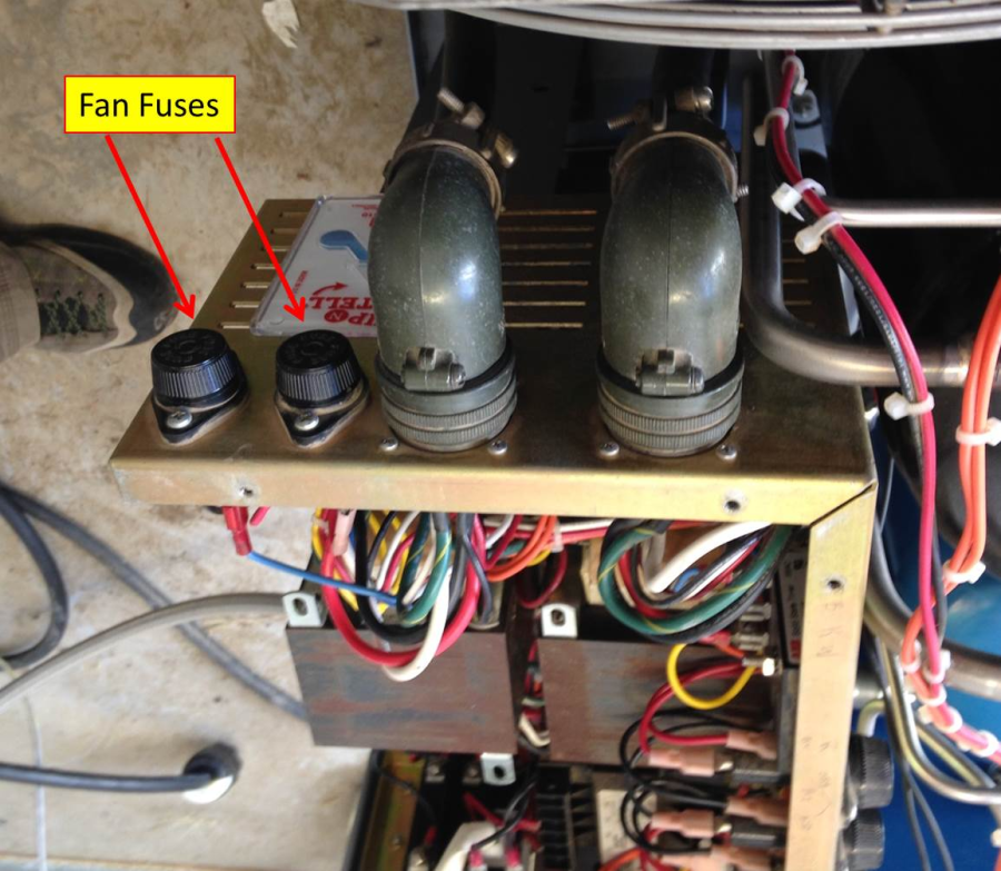
- These fuses are 2A very-slow-blow and go into two of the screw-in fuse holders on the back (West-facing) surface of electronics box. (see pic below)
- There are spare fuses in the plastic box labeled "Helium Shed; Do Not Remove"
- Pull each of the two fuses and use a DVM to test for continuity
- Replace any bad fuse
- Note the number of spare fuses remaining
- Put the side cover back on to the compressor
- Plug the compressor power cable back into the wall outlet
- Turn on the compressor
- Wait to be sure the fans are both running and that the overheat condition has been cured
- If the cold head fuse fails, the symptoms will be a working compressor, but no helium moving through the system (no wheezing, no cold head sounds, no variations in supply/return pressure gauges).
- Turn off the compressor main power
- Unplug the compressor from the wall outlet
- Remove the compressor side panels
TBD – awaiting details and pics